Map Manager
In this section the software Map Manager is presented, which was developed in the context of a master thesis at IMES. With the Map Manager, several maps can be created and connected to each other at certain points (so-called link points).
Since Sobi has to operate in different environments on campus (e.g. indoor in corridors and entrance halls, in elevators or outdoor between the institute buildings) it is necessary to create several maps between which the robot can switch. This not only reduces the size of the individual maps and thus improves the localization and the resource utilization of the computer, but also allows to use different sensor configurations for different environments.
The chapter is divided into the following sections:
Basic principle of the Map Manager
Basically, the Map Manager is superior to the SLAM process (in this case RTAB-MAP). The algorithm, manages maps created by RTAB-MAP and connects them by link points. This ensures that the robot can later plan and navigate over multiple maps. Dividing the robot’s operational area into multiple maps has the advantage that the robot can use different SLAM configurations for different environments (e.g. indoor/outdoor). Furthermore, smaller maps improve the map quality because RTAB-MAP has fewer nodes in the Long-Term-Memory (LTM) and thus a pre-selection of nodes that are eligible for loop closures is already made. In the following, the basic principle and operation of the Map Manager is explained. First, the topological graph structure is discussed, which can be abstracted from the arrangement of maps and link points. The gate detection and subsequent selection of the optimal SLAM configuration is also described. Then, the detection of topological loop closures by feature matching is explained. Finally, the tracking of the global robot position is described and the optimization of the topological graph after a loop closure.
Topological graph structure
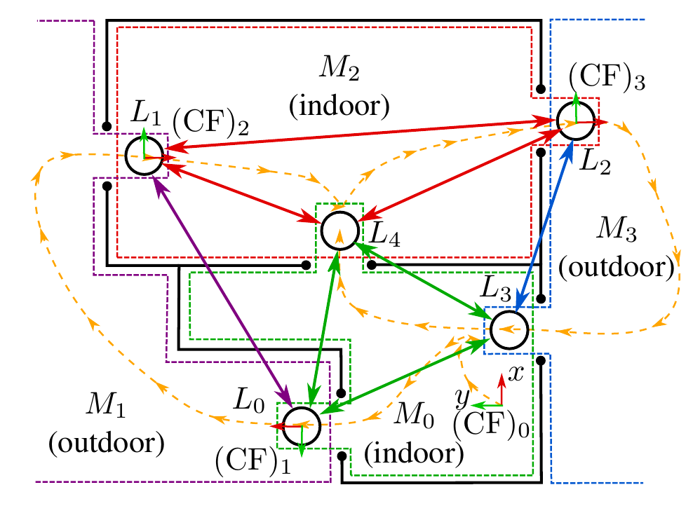
Fig. 1: basic principle of the map manager with several maps connected by link points located in the overlapping area of two maps.
Each map represents a room or outdoor area separated by doors. In Fig. 1, four maps (two indoor and two outdoor) are presented. The individual maps are indicated by colored dashed lines. For each map, the coordinate systems (CF) are plotted. The link points are indicated by circles in the overlap area of two maps in front or behind. Link-Points are connected by Edges (colored arrows). Link-Points are connected by Edges only if they are located on the same card. The color of the arrows matches the color of the map. The driven robot path for mapping is marked by the dashed orange line.
The mapping procedure for this example is as follows (the feature matching and door detection methods described here will be explained in more detail later). The start is on Map 0 after the robot has detected via laser scan data that the indoor configuration (small distances) should be used for RTAB-MAP. Then the robot drives in front of a door and sets a Link-Point Candidat, which is later important for the Loop-Closure and becomes the Link-Point L_3, as soon as the robot drives through the door there again from the other Map (3). Then the robot drives through the door on the other side of the room. The robot recognizes that the door has been passed and ends the old Map 0 behind the door. The environment is checked by the laser scan data and the outdoor configuration is used. Then the mapping for a new map is started (Map 1). In the link point 1 both maps overlap. The robot moves over Map 1 and after it passes the door, it exits Map 1 and checks based on the camera data whether it has already been to this location (or whether this link point already exists) or not. Then it starts a new map in the indoor configuration. Another Link-Point Candidate is set and subsequently the door is passed in the direction of Map 3. Link-Point 2 and Map 3 are also newly created. As soon as the robot passes the door from Map 3 to Map 0, this is automatically detected and it is checked whether the robot has already been at this location. Since the feature matching with the link point candidate set at the beginning provides a high match, the link point candidate is converted into a link point (L_3). Furthermore, no new map is started, but the old map (Map 0) is loaded again. After the robot has passed through the door towards map 2, the link point candidate is also converted into a real link point, so that the topological graph is now complete.
Door-Detection and selection of SLAM-Configuration
To detect the door, the laser scan data of the Velodyne VLP-16 is used. For this purpose, the PointCloud2 is converted to laser scan data (a 2D projection) using the ROS package pointcloud_to_laserscan. The laser scan data (range) is then derived by the angle. To detect doors, large derivatives are searched for in the laser scan data at a given angle and distance. The door must be open for the derivative to be correspondingly large.
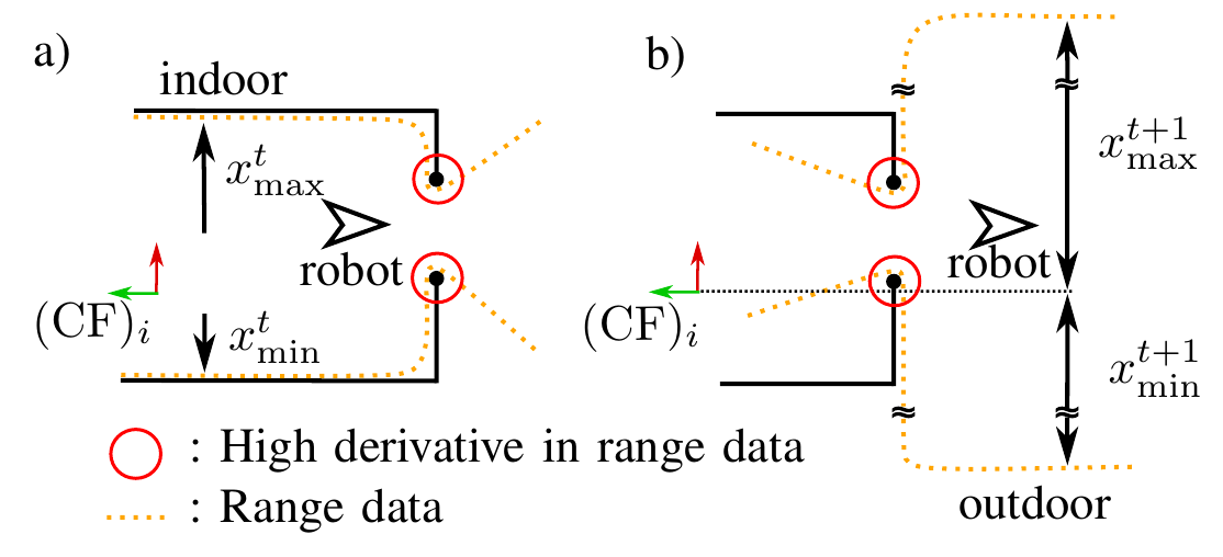
Fig. 2: criteria for door-detection: the open door causes high discharges at the position of the door jambs. This can be detected from the front as well as from the back. Also, the change (derivative) of the maximum and minimum range data is used to detect the change of the environment.
There are three criteria for the reliable detection of a door crossing, of which at least two must be fulfilled for the door to be detected. The first criterion is the detection of the door from the front by analyzing the derivatives of the laser scan data (Fig. 2 a). The second criterion is the same detection of the door from behind, i.e. after the robot has passed through (Fig. 2 b). If these two criteria are met, the door is successfully detected. However, there are doors where a wall is close to the door frame at a right angle, so the derivatives become very small at this point. For this reason, the third criterion was developed. The laser scan data is low-pass filtered and then an imaginary bounding box is placed around it (determine min/max values in x and y directions). The change of the bounding box is calculated via the derivative. If the change is very large, it indicates that one has passed through a door into another room or outdoor environment. This criterion can therefore (at most) replace a door detection from the front or back.
Low-pass filtered laser scan data is also used to determine the SLAM configuration for the new map. If the maximum distances exceed a certain limit, the long distance (outdoor) configuration is used. There are also other criteria that can be used and are switched on via the config file. Possible criteria are to measure the noise of the depth images of the Realsense cameras by PSNR (Peak Signal-Noise-Ratio) or SSIM (Structural Similarity). If the noise is too strong (e.g. because of too high distances) the Outdoor-Config is used. In addition, a CNN is implemented (ResNet18 based on the Places365 dataset) to classify the captured scene of the front camera into either indoor or outdoor.
Loop closure detection using feature matching
In order for the robot to recognize whether the link point already exists, a new link point must be created or a loop closure with an existing link point candidate exists, the current camera images must be compared with the camera image stored in the link point (candidate). This comparison is done by feature matching with SIFT features (see Fig. 3).
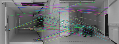
Fig. 3: feature matching between a previously captured image with the back camera (therefore rotated) of a link point candidate and with the current front camera image of the robot. Although the images are rotated, the algorithm finds many matches.
When the number of matching features (matches) exceeds a certain threshold, the loop closure is accepted. To be robust against image noise, a series of images is used for feature matching. The median is then used to evaluate similarity. Additionally, when closing a loop closure with a link point candidate, an ICP registration is performed between the point cloud stored in the link point candidate and the current point cloud. On the one hand, it increases the security that no false loop closure is detected, and on the other hand, it allows the current position of the robot in the old map coordinate system to be calculated, which is important for the creation of the link point.
Global position tracking and topological graph optimization
Until now, the robot has compared the current camera images with all existing link points and link point candidates. This costs time and is inefficient. To increase efficiency, the global position of the robot can be computed over multiple maps and consider only the link-point (candidates) that are within a search radius around the robot. To compute the global robot position, the relative positions of the maps to each other must be known. This can be calculated by the link points, since they describe the same position in the global coordinate system in the respective coordinate systems of the adjacent maps. Thus, a transformation between the two origins of the adjacent maps can be calculated. The shortest topological path between the world CS and the map origin in which the robot pose is calculated can be determined by Dijkstra’s algorithm.
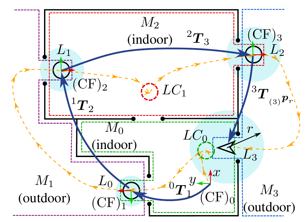
Fig. 4: global tracking of the robot pose by chaining transformations. Since the relative transformations have uncertainty (covariance), this increases as more transformations are involved (blue circle). This figure represents a mapping state from an earlier time point compared to Fig. 2.
Fig. 4 illustrates the chaining of multiple transformations and the associated variance propagation in position. As the uncertainty in position increases, the search radius also increases. In the example, only Link-Point Candidate 0 lies within the search radius and is thus used as the only option for loop closure detection. The initial uncertainty of a position is given by an estimate (variance in X,Y and theta). The variance propagation in the poses was computed using the ROS package pose_cov_ops.
After a new loop closure is found, it is possible to use the additional topological information to optimize the graph with respect to the global positions. This is done with the C++ library g2o (A General Framework for Graph Optimization). This corrects the global positions of the link points and thus reduces the error due to the variance propagation.
Mapping with the Map Manager on Sobi
This article describes how mapping works with the Map Manager on the CMR. Since this is not the automated version, no doors are automatically detected and the link points and link point candidates have to be inserted manually by ROS service calls. The state machine for the mapping can be found in sm_mapping.cpp in the package ‘‘map_manager’’. The parameters for the map manager can be set in params.yaml.
To start the mapping on the CMR, the following steps have to be executed in the console:
-
start
roscore(CMR). -
bringup(base) -
roslaunch map_manager sensor_model_full.launch(CMR) Launch the sensor and URDF model. -
rosrun map_manager rtabmap_starter(CMR). -
roslaunch map_manager sm_mapping.launch(CMR) Starts the State Machine and loads config parameters from .yaml file.
State Machine Mapping:
The states of the State Machine:
-
Initialize:initialize the state machine: initialize important parameters; query of the working directory; create the SQL database where information about link points, link point candidates and maps are stored. -
Start_Mapping:state to start mapping: checks which SLAM configuration is optimal for the environment; sends message tortabmap_starterto start RTAB map; calculates shortest topological path to the map, the robot is currently on, to initialize theGlobal Tracker. -
Mapping:state during mapping: an initial pose is set at the beginning (if necessary); continuously call theGlobal Trackerto publish the global pose. This state can only be terminated by a service call (see below). Only in this state service calls should be called to create Link-Point (Candidates)!!! -
Kill_mapping_mode:stops RTAB-MAP by killing the ROS node. -
Main_Menu:main menu with choices: record new map; mapping on old map; delete Map; delete Link-Point; abort.
During use, the user is guided through the program with the help of text outputs.
Use of ROS Services for actions during mapping:
During mapping, actions can be performed by calling ROS services. There are the following services:
-
Set Linkpoint:
(sm_mapping/set_linkpoint): sets link point to the location where the robot is. It is previously queried whether there is a loop closure with a link-point candidate or not. Link-Point position should be chosen in front of or behind a door. The actual position of the Link-Point, however, can be chosen freely. Care should be taken to ensure, that if there is a Loop-Closure with an existing Link-Point Candidate, the two positions match. -
Record Linkpoint Rear Image:
(sm_mapping/save_linkpoint_rear_img): before a link point is saved (by calling the servicesm_mapping/set_linkpoint), an image should be taken with the back camera so that the SQL database is also compatible with the automated variant later. To do this, simply call the service when the robot is still in front of the door. When the door has been passed, the other service must be called afterwards to save the link point (see above). -
Set Link-Point Candidate:
(sm_mapping/set_linkpoint_candidate): when this service is called, a link-point candidate can be stored. This should be placed in front of a door, as described in the previous article 1) Basic principle of the Map Manager
Parameters for State Machine Mapping:
The following parameters can be set in params.yaml.
-
initial_variance_x:initial variance in the X position of the robot. This parameter is important to calculate the variance propagation in the global tracker. -
initial_variance_y:initial variance in the Y position of the robot. This parameter is important to calculate the variance propagation at the global tracker. -
initial_variance_theta:initial variance in the rotation of the robot. This parameter is important to calculate variance propagation at the global tracker. -
use_global_tracker:boolean variable whether the global tracker should be enabled or not during mapping. If disabled, no global position of link points will be stored, preventing the recorded SQL database from being used with the automated approach. Otherwise, disabling this feature has no disadvantages. -
record_imgs_and_pc:boolean variable whether to record the images from the front and back camera to the link points or not. Additionally the point cloud is also recorded at a link point candidate. Only if the variable is set to true, the compatibility of the database to the automated approach is present.
Automated mapping with the Map Manager
This article describes how automated mapping with the Map Manager on the CMR works. In the automated variant, the passing of doors is automatically detected and the link points and link point candidates are automatically set by the algorithm. The state machine for the automated mapping can be found in automated_sm_mapping.cpp, in the package map_manager. The parameters for the map manager can be set in params.yaml.
To start the automated mapping on the CMR, the following steps have to be executed in the console:
-
start
roscore(CMR). -
bringup(base) -
roslaunch map_manager sensor_model_full.launch(CMR) Launch the sensor and URDF model. -
roslaunch map_manager utils_map_manager.launch(CMR) Launch the node pointcloud_to_laserscan as well as the CNN for scene classification (indoor or outdoor). -
rosrun map_manager rtabmap_starter(CMR). -
rosrun map_manager environment_detector(CMR) Starts the Environment Detector: Detects the passage of doors and the changes from the environment by laser scan data. Automatically sets the link points and link point candidates and also automatically detects the loop closures. This node replaces the manual invocation of Ros services in non-automated mapping. -
roslaunch map_manager automated_sm_mapping.launch(CMR) Starts the State Machine and loads config parameters from .yaml file.
Automated mapping of the State Machine:
The states of the State Machine:
-
Initialize:initialize the State Machine: initialize important parameters; query the Working Directory; create from the SQL database where information about Link-Points, link point candidates and maps are stored. -
Start_Mapping:state to start mapping: checks which SLAM configuration is optimal for the environment; sends message tortabmap_starterto start RTAB map; calculates shortest topological path to the map the robot is currently on to initialize theGlobal Tracker. Also starts Environment Detector via ROS message, which does not run if not mapped. -
Mapping:state during mapping: here an initial pose is set at the beginning (if necessary); continuously calling theGlobal Trackerto publish the Global Pose. During this state, the Environment Detector detects doors as they are passed through and changes in the environment. The Environment Detector exits theMappingstate as soon as the passage of a door is detected and a link point is stored or an already known link point is detected (by a loop closure). -
Kill_mapping_mode:stops RTAB-MAP by killing the ROS nodes. -
Main_Menu:main menu with choices: record new map; mapping on old map; delete map; delete Link-Point; abort.
During use, the user is guided through the program with the help of text outputs.
Notes for the use of the Automated Map Manager:
-
To set link points, the robot must be pushed in straight alignment in front of the open door. The door must be detected (to be on the safe side) three times in a row (happens automatically within about 2 seconds). Then the link point candidate is saved and the mapping can be continued normally.
-
In order for the Environment Detector to detect the passage of a door, the robot should be driven slowly and straight through the door so that the derivations at the door jambs are properly detected. For some doors, detection can be problematic if the door is made of glass (Derivatives may still be detected on the frame) or if walls are directly adjacent to the door, making the derivatives very small. If the door could not be detected properly with several attempts, the (manual) state machine must be consulted.
-
For the doors to be detected, they must be open and no object must be directly in front of or behind the door.
Parameters for the Automated State Machine Mapping:
The following parameters can be set in params.yaml.
-
config_criterion:criterion according to which the SLAM configuration should be determined automatically. -
range_thr:limit value for distance of laser scan data, from which the configuration should be used for high distances. -
ssim_thrandpsnr_thr:limit values (PSNR and SSIM) to evaluate the noise of the cameras. If the noise in the depth image is too high, the depth image is calculated from the Velodyne-data. -
initial_variance_x:initial variance in the X position of the robot. This parameter is important to calculate the variance propagation in the global tracker. -
initial_variance_y:initial variance in the Y position of the robot. This parameter is important to calculate the variance propagation at the global tracker. -
initial_variance_theta:initial variance in the rotation of the robot. This parameter is important to calculate the variance propagation at the global tracker. -
num_depth_imgs:number of depth images, which are used for image noise detection.
Parameters for the Environment Detector:
The following parameters can be set in params.yaml.
-
feature_matching_thr:required number of feature matches to accept a loop closure. -
num_last_imgs:number of taken images to detect feature matching with the stored image. When multiple images are taken, the feature matching becomes more robust against image noise, but it also increases the computation time. -
NNDR_akaze:nearest neighbor distance ratio (NNDR) for AKAZE features. -
NNDR_sift:nearest neighbor distance ratio (NNDR) for SIFT features. -
icp_fitness_score_thr:fitness score for ICP registration. If the fitness score is too large, i.e. the point clouds are too different in position and shape, the loop closure will not be accepted. -
deriv_door_thr:limit value for the derivation necessary to detect the door jambs. -
time_limit_door_detection:time limit for the complete detection of a door. The timer starts as soon as the door has been detected from the front. If the door has not been completely detected after this time, the door detection will be reset. -
deriv_range_thr:threshold for the derivative of the bounding box, of the low pass filtered laser scan data, to detect an environmental change by laser scan data (third criterion). -
low_pass_filter_size_env:filter size for the average low-pass filter for the laser scan data.
Saving the maps in .pgm and .yaml
This article describes how to save the corresponding .pgm and .yaml files based on the SQL databases created by RTAB-Map. In this procedure the conversion of the data has been automated. In principle, each individual database can also be manually converted to a .pgm and .yaml as described here.
To store the .pgm and .yaml automatically for each map in the working directory (must be specified at the beginning), the following must be done on the CMR:
-
roscore(CMR). -
rosrun map_manager save_map:iterates through all maps present in the database and calls themap_saverthrough a ROS message. Additionally startsrtabmap_roswith thertabmap_starterby sending a ROS message. -
rosrun map_manager map_saver_starter:starts themap_saveras soon as the signal comes from the node ‘‘save_map’’. -
rosrun map_manager rtabmap_starter:itartsrtabmap_rosas soon as the command fromsave_mapcomes.
First start all nodes. Then enter the directory at the save_map node and wait until “DONE, saved all maps!” is displayed. After the ROS node save_map has iterated through all maps, all nodes can be turned off. Unfortunately, the commands have to be swapped out to three different nodes, otherwise automation in the code would not be possible. The saved .pgm and .yaml files can be found in the same directory as the SQL databases of RTAB-MAP.
Visualization in Rviz
With the help of the ROS node rvizgraph link points can be visualized in Rviz. To do this, the map manager must be running in mapping mode (as described in 3) and 4)). The node can be started by the command rosrun map_manager rvizgraph. It gets the current map ID via the ROS topic /map_manager/cur_map_id. This is necessary because the link points that are on the current map should be displayed in the map coordinate system. All other link points are represented in the world coordinate system, which is not as accurate.
Therefore, the ROS node sends visualization_msgs::Marker on the topic map_manager/local_linkpoints_rviz or map_manager/global_linkpoints_rviz. These markers can be easily added in Rviz. It is important to note that the markers can only be seen if the coordinate systems map and world also exist, i.e. if RTAB-MAP and the state machine for the mapping are running properly.
Troubleshooting
Here is a collection of problems that can occur in connection with the Map Manager and RTAB-MAP. This list will be extended continuously.
-
RTAB-MAP does not receive data (yellow warning appears): as soon as RTAB-MAP does not get a required topic, RTAB-MAP as a whole does not work. Check if all topics with the appropriate names are published and available. Otherwise, check if the sensor drivers need to be restarted or the nodes
rgbd_syncorregister_velodyneare working properly. -
RTAB-MAP does not find loop closures: has the correct SLAM configuration been used? Has the same (or similar) path also been traversed in the correct orientation? Does the sensor system provide all required data? Has the appearance of the environment changed drastically (lighting conditions or objects that were not there before)?
-
The Environment Detector does not detect the door: has the door been passed through straight and slowly? Is no one standing in the door, or can large derivatives be formed? Is there a wall adjacent to the door so that the derivative becomes small? With glass doors the detection can be faulty. Sometimes it helps to restart the Environment Detector. If you can’t get the problems under control, you have to use the State Machine for manual mapping.
-
The Global Tracker publishes an incorrect global pose: make sure that the link points are not stored redundantly and that the topological graph is otherwise intact. Errors in the topological graph will also cause errors in the global tracker.
-
No loop closure is detected by feature matching: have lighting conditions or the scene changed? Is the link point or link point candidate in the search radius of the robot (only relevant for automated mapping)?
Citing
If you use this software for your research, please cite the following publication:
Map Management Approach for SLAM in Large-Scale Indoor and Outdoor Areas
Ehlers, S., Stuede, M., Nuelle, K., Ortmaier, T.
IEEE International Conference on Robotics and Automation (ICRA) 2020