Electronic devices and components
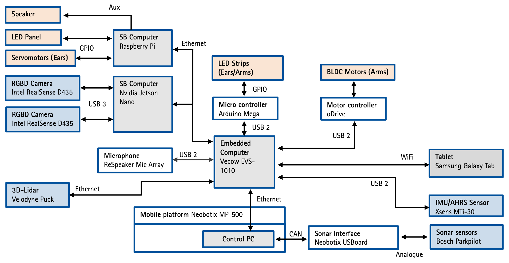
This chapter describes the general structure of the robot’s hardware. The following figure shows a general overview of all hardware-related components of the robot:
The structure of the following section is divided into the subsections base, torso and head.
Sobi: Base
Sobi’s base consists of the Neobotix MP-500 mobile platform.
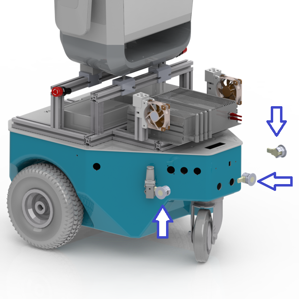
The platform, shown here in blue, consists of two drive wheels and a running wheel. Both drive wheels have a motor, so that a pure rotation of the robot is possible. A control computer is installed in the base, to which the ultrasonic sensors are connected via the Neobotix USBoard. These three ultrasonic sensors are marked here with a blue arrow. They are used to send a signal to block the drives as soon as there is an obstacle in a certain radius around the robot (see also Sensor topics and transformations). For further information about the platform, we refer to the official documentation of the MP-500 platform
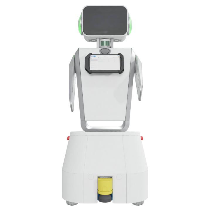
In this image, the entire robot is shown. A S300 2D safety laser scanner from SICK is attached to the bottom of the base. The laser sensor and the drives are a self-contained system, so that it can block or limit the drives independently of the overall (ROS) system. The sensor is divided into three detection areas, which are defined by the respective distance to the sensor. A distinction is made between the first detection range, in which there is no intervention in the drives. In the second detection range, which is a subset of the first, the maximum velocity is reduced. Finally, the critical range is defined, in which the drives block directly as soon as an obstacle is detected in this range. The sensor data of the 2D laser sensor are available in the ROS framework, which is discussed in more detail in the chapter of Sensor topics and transformations).
IMPORTANT: The robot is powered at 24 V by four lead-acid batteries. This means that there is a permanent voltage at the batteries even if the robot is switched off!
Sobi: Torso and head
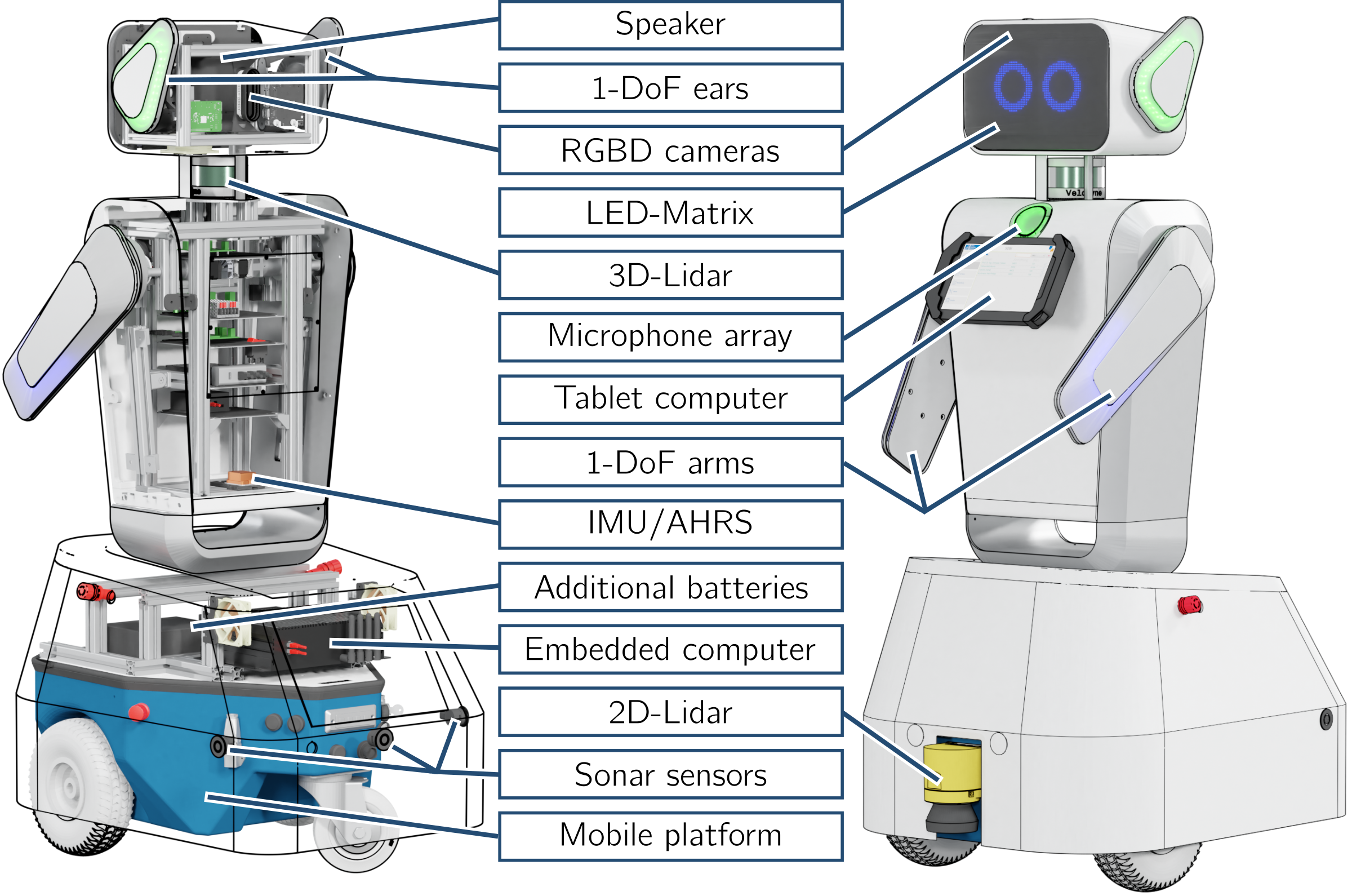
The torso and the head were designed by the Institute for Mechatronic Systems (imes). Inside them there are some components, which are shown in the following picture.
| Sensor | Description |
|---|---|
| 2D Lidar | The 2D laser scanner (SICK S300) is primarily used for safety-related functions. It is a safety system decoupled from the ROS framework. The data can also be accessed in the ROS framework |
| Embedded Computer Vecow EVS1000 | The embedded computer Vecow EVS 1000 is the main computer of the entire robot system. The Rosmaster of the entire communication system of the robot is executed on this computer. |
| Tablet | The tablet is a Samsung Galaxy Tab A (10.1 inch, 2016), serves as an input devices for users of the robot. |
| Microphone | The microphone is an array microphone (ReSpeaker Mic Array v2). In addition to normal speech recognition, it can detect the direction from which the sound is coming via direction-of-arrival (function currently unused). Furthermore, algorithms like beamforming and static noise suppression are supported. |
| RGBD cameras | Two RGB-D cameras (Intel Realsense D435) are mounted in the head of the robot. These are depth imaging cameras and thus provide a depth image in addition to the RGB image. |
| Jetson Nano | The two Realsense cameras are connected to the Jetson Nano, which is installed in the head. On the Jetson the corresponding drivers and ROS nodes are executed to provide the RGB, depth image and the point clouds to the ROS framework via Ethernet. |
| Raspberry Pi | In addition, a Raspberry Pi is installed in the head. This is a single board (SB) computer and also part of the ROS framework. Here the LED panel and the servo motors are connected, which are also controlled by individual ROS nodes. |
| Emergency Stop Switch | Two emergency stop switches are attached to the robot, which directly block the wheels when pressed. |
| IMU/AHRS | The Inertial Measurement Unit (IMU) or the AHRS (Attitude Heading Reference System) is located at the bottom of the torso and is used for motion detection of the robot. An integrated Kalman filter directly provides the absolute orientation. |
| BLDC Motors | The BLDC (Brushless Direct Current) motors are used to drive the arms. They are equipped with a gearbox (reduction ratio of 1:64) and an encoder. The motors are controlled via the underlying ODrive. |
| oDrive | The oDrive serves as a controller for the BLDC motors and is connected to the main computer via USB. |
| Velodyne 3D Laser Scanner | The 3D laser scanner (Velodyne VLP 16 PUCK) is located in the neck. It provides three-dimensional laser data in the ROS framework as a point cloud including the measured intensities. |
| Ears | In the head there are two servo motors, which are used for the movement of the ears. These are controlled using the Raspberry Pi and the pigpio library. |
| LEDs | The ears and arms are also equipped with RGB LED strips that can be controlled with the Arduino. The strips offer the possibility to display any RGB colors in 8-bit. In the head is an additional LED panel, which animates the eyes of the robot. The panel can display any BMP files in 64x32 Px format as well as GIF files in the same format. The panel is controlled by the Raspberry Pi using the Rpi RGB LED Matrix Library |