Sensor topics and transformations
The entire communication structure of the robot is based on the ROS framework. Accordingly, the rosmaster runs on the main computer, whose position is described on the page Devices and components , since all communication is controlled or processed via this computer. All other computers in the robot system are connected via Ethernet through the switch in the torso.
Sensor data
All sensor data is provided in the ROS framework. It should be noted here that the data from the 2D laser sensor is read in and published from the base computer inside the MP-500 platform, and the camera data is read in from the Jetson Nano and published in the ROS framework. The following is a tabular list of the main topics of the system.
| Data | Topic | Message | Description |
|---|---|---|---|
| 2D Laser Data | /base/laser/scan_filtered | sensor_msgs/LaserScan | Filtered laser data of the 2D laser sensor. The filtering is necessary to prevent the robot from detecting its own front in the laser scan. |
| 3D laser data | /velodyne_points | sensor_msgs/PointCloud2 | Point cloud of the 3D laser sensor |
| 3D laser data | /velodyne_laserscan | sensor_msgs/LaserScan | Point cloud of the 3D laser sensor projected onto the XY plane of the base_link coordinate system |
| Front camera | /cam_front/color/image_rect | sensor_msgs/Image | Rectified front camera RGB image |
| Front camera relayed | /cam_front/color/image_rect_relay | sensor_msgs/Image | Front rgb image, relayed on main computer. |
| Front camera (depth image) | /cam_front/aligned_depth_to_color/image_rect | sensor_msgs/Image | Depth image of front camera |
| Front camera (point cloud) | /cam_front/depth_registered/points | sensor_msgs/PointCloud2 | Registered (with color values) point cloud of the camera |
| Back camera | /cam_back/color/image_rect | sensor_msgs/Image | RGB image of the back camera |
| Back camera | /cam_back/color/image_rect_relay | sensor_msgs/Image | RGB image of the back camera, relayed on main computer |
| Back camera (depth image) | /cam_back/aligned_depth_to_color/image_raw | sensor_msgs/Image | Depth image of the back camera |
| Back camera (point cloud) | /cam_back/depth_registered/points | sensor_msgs/PointCloud2 | Registered (with color values) point cloud of the camera |
| IMU | /imu/data | sensor_msgs/Imu | Measurement values of the IMU |
| Odometry | /odometry/filtered | nav_msgs/odometry | Odometry filtered with the EKF |
| Ultrasound | /base/relayboard_v2/usboard/measurements | sensor_msgs/Range | Values of all ultrasonic sensors |
| Speed | /cmd_vel | geometry_msgs/Twist | Target velocity is published to this topic |
| Speed target motor control | /cmd_vel_safe | … | Outside the already provided nodes. Should never be published to this topic |
Information for the use of camera topics
Since the camera images are published by the Jetson Nano via network, it is not recommended to directly subscribe on the uncompressed image topics from the other computers. Instead, when the launch files from cmr_osare used together with the camera drivers a node will be started that subscribes to the compressed camera topics and converts them to an uncompressed image (_relaysuffix in the table). This topic should be used if processing of raw images is necessary. Otherwise, compressed images should always be preferred.
Communication structure movement
The following figure gives an overview of the communication structure of the basic topics for motion.
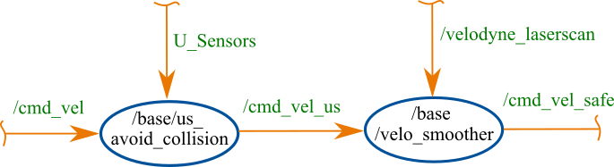
As soon as something is published to the topic /cmd_vel, the node /base/us_avoid_collision subscribes this. This node additionally subscribes to the measurements of the sonar sensors. If these detect an object at a distance below a defined threshold, the node publishes a translational and rotational velocity of zero to the topic /cmd_vel_us. If there is no object nearby, the same message published by the topic ‘‘/cmd_vel’’ will be published to the topic /cmd_vel_us. The node /base/velocity_smoother receives this message and additionally subscribes to the laser scan data /velodyne_laserscan. If the resulting velocity vector of the message /cmd_vel_us is greater than zero, the node /base/velocity_smoother uses the laser data to check in which distance the nearest obstacle is located. Depending on this, a maximum velocity is set to which the vector of velocity is limited. This scaled vector is then published on the topic /cmd_vel_safe, which directly subscribes the node for controlling the kinematics. Because of this you should never publish directly to cmd_vel_safe, because in this way the safety functions are bypassed!.
TF-Tree
Within the robot some coordinate systems are defined. The URDF model is used for referencing among them. The basic structure of the coordinate systems is shown in the following figure.
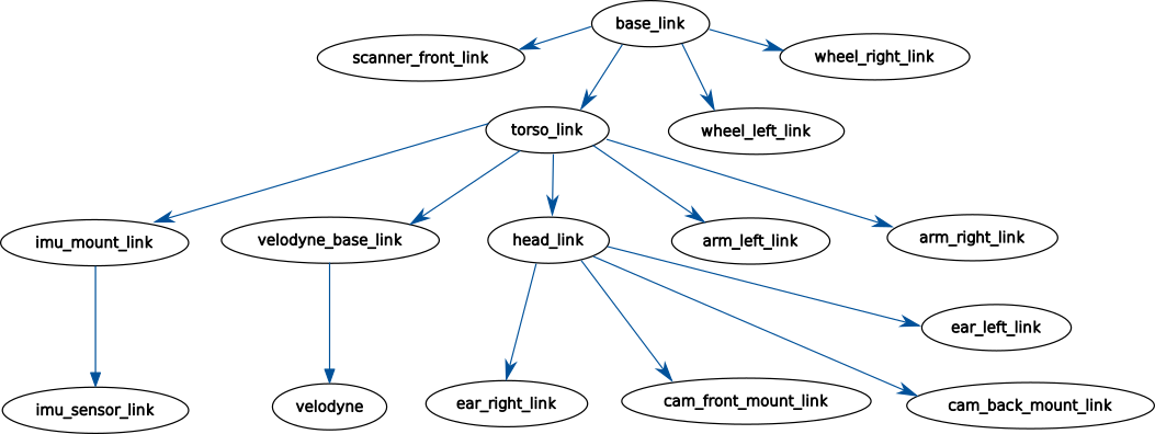
The base_link coordinate system is the main coordinate system of the robot. All other coordinate systems of the robot are referenced to this one. The base_link coordinate system is centered in the middle between the robot’s drive wheels on the ground, with x facing forward. The coordinate systems of the 2D laser scanner, the tires and the torso are referenced from this. From the torso_link all components inside the torso are referenced. In addition, the head is referenced to the torso. The head_link subsequently references the cameras and the ears. In the figure, only the basic coordinate systems are shown. For example, in the camera there are some other coordinate systems for the different lenses. In addition, the coordinate systems odom and map are necessary for navigation. The following figures show the basic coordinate systems on the robot.
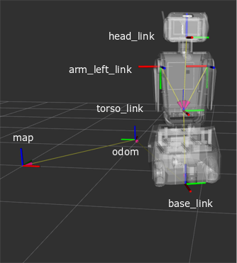
In the left figure, the map and odometry coordinate systems are on the xy plane. The link between the these and the body-fixed coordinate systems is the transformation between the odom and base_link coordinate systems. In addition, the other two main coordinate systems of the robot torso_link and head_link, which reference all other components in the robot, are shown. In the right figure, the coordinate systems of the main sensors are shown. The camera coordinate systems are rotated around the x-axis, the y-axis and z-axis, respectively, as the back camera is rotated by 90°. It is noticeable that the velodyne coordinate system has a twist of about 45° with respect to the base_link. Looking at the robot, it can be seen that the velodyne is also twisted on the robot.